

A cable gland inspection checklist helps electrical and commissioning teams verify installed cable entries against the approved design before equipment is released for energization. For EPC projects in Jamnagar, Gujarat, connect each gland to the cable data, enclosure entry, drawings and manufacturer instructions. A “Pass” mark is useful only when the requirement and supporting evidence are clear.
This guide sets out 12 checks and explains what to record when an item fails. Use it with the approved inspection and test plan (ITP), applicable installation requirements and product instructions. It is not an energization permit or a substitute for the project’s authorised release process.
Download the Printable Cable Gland Inspection Checklist
Use the printable PDF to record each result, supporting evidence and defect reference. It can accompany the project’s inspection record or be adapted to the approved site form. It does not set acceptance criteria; use the project documents and gland manufacturer’s instructions.
Mark each item Pass, Fail or Not Applicable and reference the drawing, datasheet, certificate or inspection record used as evidence. Give a reason for every Not Applicable result. If the project requires a controlled cable gland inspection form PDF or QA/QC record, use that approved document and keep this checklist as a supporting aid.
What a Pre-Energization Cable Gland Inspection Confirms
A site inspection checks the installed cable entry against the approved design and assembly instructions. It is different from a factory test of the complete gland. IEC 62444 addresses cable gland construction and performance requirements and tests; a field inspection checks the installed product, visible condition, documents and project acceptance records. See the IEC 62444 standard overview.
The inspection should be done by competent personnel under the site’s safe-work arrangements. Do not loosen, dismantle or adjust a cable gland while the connected equipment is energised. Where access or a corrective action requires opening an enclosure or disturbing a termination, follow the approved isolation, permit and verification procedure first.
A cable gland installation procedure may be a manufacturer’s instruction or a project method statement. The checklist helps verify requirements and capture evidence; the approved ITP defines inspection timing, responsibilities and required records.
12 Cable Gland Checks Before Energization
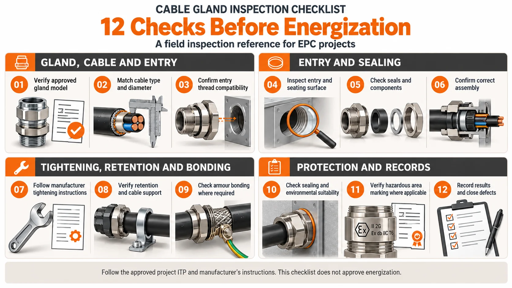
Use this table during the walkdown. Acceptance criteria depend on the gland design, cable construction, enclosure, environment and project specification. Similar appearance or a matching size on a neighbouring termination is not sufficient evidence.
| No. | Inspection check | What to verify or record |
|---|---|---|
| 1 | Approved gland model | Installed model and type match the approved schedule and applicable documentation. |
| 2 | Cable type and diameter | Construction and measured dimensions fall within the documented suitability and clamping range. |
| 3 | Entry thread compatibility | Thread type, size and equipment entry match the drawing and product requirements. |
| 4 | Entry and seating surface | Entry is suitable, properly prepared and free of visible damage that could affect seating. |
| 5 | Seals and components | Required seals, washers and components are present, correct and undamaged. |
| 6 | Assembly arrangement | Components are fitted in the required order and the cable is prepared as instructed. |
| 7 | Tightening | Assembly follows the manufacturer’s instructions; any specified torque is documented. |
| 8 | Retention and support | Cable is retained as intended and has suitable support for its installation conditions. |
| 9 | Armour bonding | Where required, armour clamping and electrical continuity meet the design and test criteria. |
| 10 | Environmental protection | Installed arrangement is suitable for the specified ingress, temperature and exposure conditions. |
| 11 | Hazardous-area documents | Where applicable, marking, certificate details and installed model are consistent with approved records. |
| 12 | Inspection record | Results, evidence and defects are documented, and required corrective actions are closed. |
Confirm the Gland, Cable and Entry Match
Checks 1 to 3. Compare the installed gland marking or model with the approved schedule, equipment drawing and product documents. If it cannot be identified, record the discrepancy. Exgrip’s Cable Gland Selection Chart is a reference, not a substitute for checking the actual cable and current product data.
Where necessary, measure the cable’s outside diameter and compare it with the specified clamping range. Conductor cross-sectional area alone does not confirm gland fit. Armoured, unarmoured and screened cables may require different arrangements despite similar nominal conductor sizes.
Check the entry thread type and size against the enclosure drawing. Similar nominal diameters do not guarantee compatibility. Look for cross-threading, poor engagement, an unsuitable clearance hole or an unapproved adapter, and record the actual entry details.
Inspect Entry Condition, Components and Sealing
Checks 4 to 6. Inspect the entry plate and seating surface for burrs, damage, corrosion, distortion or paint build-up that could affect the interface. Confirm unused entries are closed with the specified blanking element. A correctly selected gland does not make an open entry acceptable.
Compare the assembly with the manufacturer’s instructions. Confirm that required sealing rings, washers, shrouds and other components are present and undamaged. Do not add sealant, substitute washers or remove components unless the approved instructions permit it.
A cable gland sealing inspection must consider the relevant cable seal and gland-to-enclosure interface, not just the visible outer nut. If a required interface cannot be seen without dismantling, record the limitation and follow the approved inspection method instead of assuming it has passed.
Verify Tightening, Retention and Bonding
Checks 7 to 9. Look for incomplete assembly, displaced seals or unexpected cable movement during an approved retention check. Follow the manufacturer’s sequence for the body, locknut and compression components. There is no universal torque value for every design. Where torque verification is specified, record the instruction, required value and method used.
Check cable support against its weight, routing and expected movement. A gland’s retention function does not mean it must carry every route load. Where the design calls for separate cleats or clamps, verify them; record any side pull or strain at the termination.
For armoured cables, verify the specified armour termination and test bonding or earth continuity where required. A metallic gland’s presence alone does not pass a cable gland earth continuity check. Record the test reference and result; use the project’s acceptance criterion rather than inventing a resistance limit.
How to Record Cable Gland Inspection Results
An inspection record should let another engineer understand the check without repeating the walkdown. Link the controlled form or inspection report to the equipment tag, cable number, drawing revision and ITP. Keep the form’s document number and revision visible and retain the completed record in the project quality file.
| Record field | What belongs in it |
|---|---|
| Identification | Equipment tag, cable tag, location, gland model and termination end. |
| Inspection reference | Drawing, datasheet, ITP step, instruction or applicable certificate reference. |
| Result | Pass, Fail or Not Applicable, with a reason for Not Applicable. |
| Evidence | Measured dimension, continuity test reference, photograph number or observation where applicable. |
| Defect and closure | Nonconformance number, corrective action, reinspection result and required sign-off. |
Use the printable cable gland inspection checklist PDF as a field prompt, not a substitute for the controlled site record. The record should be legible, dated, attributable to the inspector and traceable to the equipment. If evidence is missing, record the outstanding item instead of marking it complete.
What to Do When a Cable Gland Fails Inspection
A failed check needs a disposition, not just a comment. If the gland, seal, entry or bonding result fails its stated requirement, do not mark the item accepted. Follow site isolation and safe-work procedures before adjusting or opening an electrical termination.
- Identify the defect. Record the cable tag, equipment tag, exact location and failed inspection criterion.
- Refer it to the responsible person. The competent installation, engineering or QA/QC authority determines the approved correction. Do not improvise a substitution on site.
- Correct the installation. Use the approved component and the manufacturer’s assembly instructions. Replace damaged parts where required rather than hiding the defect with an unapproved sealant or accessory.
- Reinspect and close. Repeat the affected check, record the new evidence and obtain the sign-off required by the project ITP.
Keep the failed result visible and link it to the corrective action, so the record shows the actual history. Energization approval remains with the personnel designated by the project’s electrical safety and commissioning process.
How the Checklist Fits an Inspection and Test Plan
An inspection and test plan defines stages, characteristics, acceptance references, responsibilities and records. A useful public example is the Engineers India Limited inspection and test plan for junction boxes and cable glands. It is an example of project documentation, not a universal checklist. Use the currently approved ITP for your project.
BSI lists BS 6121-5:2005 as a code of practice for selection, installation and inspection of cable glands and armour glands within its stated scope. Its published scope excludes fibre-optic and mineral-insulated cables and glands for explosive atmospheres. For a hazardous-area installation, consult the applicable explosive-atmosphere requirements and approved project documentation rather than relying on that code alone.
Keep the checklist and ITP aligned. If the ITP requires a witness point, measurement or record missing from the template, add it to the controlled project form. Mark a check Not Applicable with a reason rather than deleting it.
Additional Document Checks for Hazardous Areas
In a classified area, confirm that the gland and entry arrangement match the approved hazardous-area documents. Check the exact model, marking, certificate reference and installation limitations. A certificate for a similar-looking model or different variant is not evidence for the installed product.
Exgrip’s technical page provides product references for document review. Confirm the current certificate scope against the actual model and project requirements. An IP rating or metal construction alone does not establish hazardous-area suitability.
Conclusion & Call-to-Action
A reliable cable gland inspection record connects each check to a requirement and evidence. It should be completed consistently and traceable to the cable, entry, product documents and approved ITP. A completed form is not a substitute for engineering judgement or energization authorization.
Before closing the inspection, resolve defects and confirm acceptance by the authorised project team. Use Exgrip’s selection chart and product range when checking product references.
📩 Talk to our technical team today at Exgrip.com
📞 Or call us directly for quick assistance!
Contact Us:
📞 Phone: +91 9537118899
🌐 Website: www.exgrip.com
📩 Request a Quote: Contact Page
FAQs
When should a cable gland inspection be completed?
Complete it at the stage specified by the project ITP, usually after installation and before release for commissioning or energization. Reinspect a disturbed or reworked termination as required by the approved procedure.
What should a cable gland inspection checklist include?
Include identification, compatibility, entry and sealing condition, assembly, retention, applicable bonding, environmental and document checks, plus defect closure. The approved project requirements determine acceptance criteria.
Does every cable gland require a torque test?
No universal torque value applies to every design. Follow the manufacturer’s instructions and record a torque value only when the applicable instruction and approved inspection method require it.
How is armoured cable gland inspection different?
It includes the specified armour termination and applicable bonding or continuity checks. Use the cable construction, gland instructions, design and test procedure; arrangements are not identical for every armoured cable.
Can a visual inspection confirm IP protection?
It can identify visible damage, missing components or poor seating, but it cannot alone prove the completed enclosure meets its specified IP rating. Follow product documentation and project verification requirements.
Is this checklist suitable for hazardous areas?
It can prompt document checks, but it does not replace hazardous-area installation requirements or competent inspection. Match the actual model and certificate scope to project documents.
Where can I find product-selection information after inspection?
Use Exgrip’s Cable Gland Selection Chart as a starting reference, then confirm the final model and size against actual cable data and current product documents.